Introduction — A Question of Motion, Data, and Responsibility
Have we truly aligned our expectations for electric drive systems with how they behave on the factory floor? I ask this because the choices we make today ripple across uptime, energy bills, and user safety. A motor controller sits at the heart of that decision — it governs torque, speed, and efficiency in ways that feel abstract until a line stops (or a robot overshoots). Recent industry surveys suggest many teams under- or over-spec their drives; we see mismatches between rated inverters and real-world loads. So: how do we match requirements to reality without wasting capital or risking downtime? I want to walk you through a clear, practical view — measured, yet candid — so teams can choose wisely and act with confidence. — Let’s move into the deeper issues behind common choices and failures.
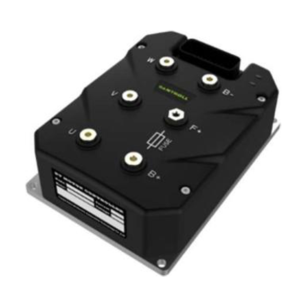
Uncovering Failures in Conventional Motor Control Solutions
motor control solutions often promise out-of-the-box simplicity, but I’ve seen the same problems repeat: thermal stress, inefficient PWM algorithms, and poor handling of torque ripple in mixed loads. Technical faults are not always hardware defects; sometimes they stem from mismatched control strategies or overlooked sensing needs. For example, teams pick sensorless control to cut costs, but then face transient instability during low-speed startup. Look, it’s simpler than you think — the issue is a systems mismatch, not always a bad part. I believe the real failure mode is planning: controllers are specified by peak ratings instead of duty cycle, and designers ignore harmonic content and switching losses. We must think beyond nameplate current and include thermal impedance, MOSFET switching loss, and the impact of long cable runs on EMI. When I audit setups, I often find insufficient derating for ambient temperature and no fallback for sensor faults — small oversights that cost production time. So what are the consequences? Higher mean-time-to-repair, inconsistent speed control under variable loads, and needless energy waste. These are not theoretical; I’ve measured efficiency drops of several percentage points when FOC tuning was left to default settings. (That adds up.)
Why do these gaps persist?
Partly because teams accept vendor defaults, and partly because integration between power converters, control firmware, and mechanical design is treated as “someone else’s job.” I urge you: test under real duty cycles, not just steady-state bench tests. You’ll save time and prevent surprises.
New Principles for Better BLDC Motor Controller Design
Moving forward, I favor approaches that embrace sensor fusion, adaptive control, and thermal-aware design. A modern bldc motor controller should combine reliable current sensing, robust PWM algorithms, and smart thermal protection that adapts to load patterns — not just trips on a fixed threshold. We can explain the principle simply: monitor the right signals, adapt the control law, and protect proactively. Practically, that means closed-loop field-oriented control (FOC) tuned for the application, combined with temperature-aware derating and EMI mitigation strategies. These are engineering patterns you can apply whether you run conveyors, drones, or robotics cells. I’ve worked on projects where adding a modest current-sensing upgrade and retuning the FOC cut energy use and improved torque consistency. — funny how that works, right?
On the implementation side, consider distributed edge computing nodes that handle local diagnostics and reduce communication latency to the central controller. That architecture lowers the chance of a single point of failure and gives you richer telemetry for predictive maintenance. We should also pay attention to component choices: choose MOSFETs or IGBTs with switching characteristics matched to your carrier frequency, and keep an eye on power converter thermal paths. These principles aren’t sexy, but they’re practical and measurable. I like to ask teams to run three tests: slow-speed start under load, thermal soak at expected ambient, and an EMI susceptibility sweep. The results tell you far more than datasheet specs.

What’s Next — Practical Metrics and Next Steps?
To make this actionable, here are three concrete evaluation metrics I recommend you use when comparing controllers: 1) Thermal headroom under expected duty cycle (not peak), 2) Closed-loop stability margin across speed and load range, and 3) Real-world efficiency across the operating envelope (not just at one point). These metrics give you a balanced view of durability, control quality, and operating cost. In my experience, teams that adopt these measures end up with fewer surprises and better ROI. Well, here’s the thing — you don’t need exotic tools to start: a calorimeter-style test (or even well-instrumented runtime logs) will reveal most issues.
In closing, I’m convinced that thoughtful matching of control strategy, hardware, and real-world testing beats marketing claims every time. We should choose solutions that respect thermal realities, provide clear diagnostics, and allow adaptive control. If you want a practical partner that understands these trade-offs, check Santroll — they’ve built modular platforms and support materials that make rigorous testing and integration less painful. I hope this helps you weigh options more clearly and act with confidence.